

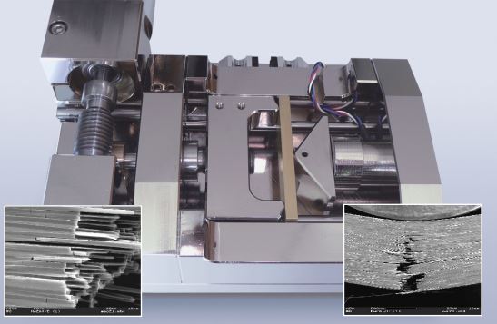
Bending Module 200 to 5000 N For 3- and 4-Point-Bending (Top view)
Description
This deformation device was originally designed to fit underneath the cantilever of an AFM.It is manufactured high-vacuum compatible, so you may also use it in the SEM. Changing from a 3-point bending to 4-point bending is a matter of a few seconds, just exchanging the “anvil” on which the specimen rests in center. The specimens should be 35 to 50 mm long, no wider than 10 mm, and up to 4 mm thick. The design is based upon two important thoughts: the whole device is extremely rigid,
therefore almost no intrinsic flexure is detectable. Another advantage is the ultra-fine movement resolution of the load frame. Both these features are important with very brittle specimens, such as ceramics: after the finest initial cracks have formed, the specimen will not fly apart spontaneously. The bending process can be continued slowly, with extraordinary well defined load increase.
Applications:
Static or dynamic observations of surface changes under controlled mechanical load; crack growth, delamination phenomena, formation of slip planes etc. Metals, ceramics, glass, ceramic bulk materials or layers, galvanic coating, soldered or welded joints, minerals, wood, organic materials
Specification
Load Ranges:
200 N, 500 N, 1000 N, 2000 N, 5’000 N load cells vailable. Others upon request.
Specimen dimensions (maximum sizes): 50 mm x 10 mm x 4 mm.
Deformation speed range: 0,2 to 20 µm/sec. Other speeds upon request.
Displacement range: 0 to 5 mm per experiment.
Electrical connection: 220 or 110 VAC.
Dimensions in mm (width/length/height): 100 mm (170 with heavy duty motor) x 130 mm x 55 mm
Accesories
Choice between manual controller (Starter system), and microprocessor controller (DDS-3) with interface and software (MDS) for PC-operation.